|
|
- Timing with germanium detectors
- Energy spectroscopy at ultra-high count rates
- Selectable filter for pulse shaping
- Signal-to-noise ratio optimization
|
- Continuously adjustable gain X2 to X250
- Pole-zero cancellation
- DC-coupling
|
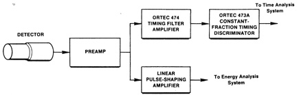
| The Model 474 Timing Filter
Amplifier is especially designed to shape pulses and permit
optimizing the signal-to-noise ratio for timing measurements. The
Model 474 is particularly suited for use with an ORTEC
Constant-Fraction Timing Discriminator in timing applications with
germanium or silicon charged-particle detectors (Fig.
1). It derives its input signal directly from the preamplifier
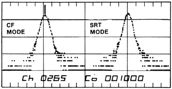
output. The timing spectrum in Fig.
2 illustrates the performance obtainable with the Model 474
shaping the germanium detector pulses before they are furnished to
the discriminator. Tables 1
and 2
give typical performance data for various ORTEC germanium
detectors. |
| The fast rise time, high output
drive, and high gain capabilities of the Model 474 make it useful
for other applications, such as timing with systems utilizing
low-gain photomultiplier tubes. In addition, the pole-zero
cancellation network, the dc-coupling, and the time-invariant
baseline restorer permit energy spectroscopy with scintillation
detectors and Si charged-partical detectors at ultra-high count
rates. |
| A wide variety of input pulse
shapes can be filtered as required for optimum signal processing.
The Model 474 combines continuously adjustable gain (X2 to X250)
with separately selectable Integrate (ti) and Differentiate (td) time constants for proper pulse
shaping, making this unit and important asset for time
measurement. |
|
PERFORMANCE |
| Input Amplitude Range
0 to ±1 V signal, 0 to ±5 V dc offset; maximum input
±5 V total. |
| Output Amplitude
Range 0 to ±5 V with a 50-W load. |
| Noise For
maximum gain, rms noise referred to the input is £10 µV with ti = td = 200 ns or £50 µV with filter out; measured using a
Hewlett-Packard 3400A true rms meter. |
| Rise Time £10 ns with filter out or ~2.2 ti for other
selections. |
| Nonlinearity
£±0.05% at midband frequency over ±5
V range. |
Temperature
Instability
DC Level £±25µV/°C referred to the
output.
Gain £±0.06%/°C.
Specifications over 0 to
50°C range. |
|
ELECTRICAL AND
MECHANICAL |
| Power Required
+24 V, 65 mA; -24 V, 45 mA; +12 V, 160 mA;
-12 V, 180 mA. |
| Dimensions
NIM-standard single-width module 3.43 x 22.13 cm (1.35 x 8.714
in.) per DOE/ER-0457T. |
Weight
Net
1.0 kg (2.4 lb)
Shipping 2.5 kg (5.4
lb) | |
|
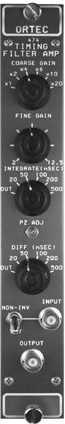
CONTROLS |
| COARSE GAIN
Front-panel 6-position switch for selection of X1,
X2, X4, X6, X10, or X20. |
| FINE
GAIN Front-panel single-turn potentiometer,
continuous from X2 to X12.5. |
| PZ
ADJ Front-panel screwdriver adjustment to
compensate for the preamplifier decay time
constant. |
Time
Constant Two 6-position switched on front
panel:
INTEGRATE RC time constants:
OUT (equivalent to 4 ns), 20, 50, 100, 200, and 500
ns.
DIFF RC time constants: OUT
(equivalent to 0.2 ms), 20, 50, 100, 200, and 500
ns.
NOTE: With Differentiate and
Integrate in the OUT position, the passband is 1 kHz to 35
MHz. |
| NON INV/INV
Selects inversion or non-inversion of the input
signal. |
|
INPUT |
| Positive or negative polarity
selectable by front-panel switch; amplitude 0 to ±1 V;
protected to ±6 V dc and to ±100 V at 10% duty factor
integrated over 1 s; impedance 100 W,
dc-coupled; front-panel BNC connector. Accepts a ±5 V dc
offset, maximum input (signal plus offset) limited to ±5
V. |
|
OUTPUTS |
OUTPUT
Front-panel BNC connector.
Amplitude 0 to ±5 V;
rise time £10 ns for filter out (2.2
ti for other filter
selections). Impedance <1 W,
dc-coupled. |
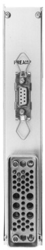
| Preamplifier
Power Rear-panel standard ORTEC power
connector, Amphenol
17-10090. | | |